loading


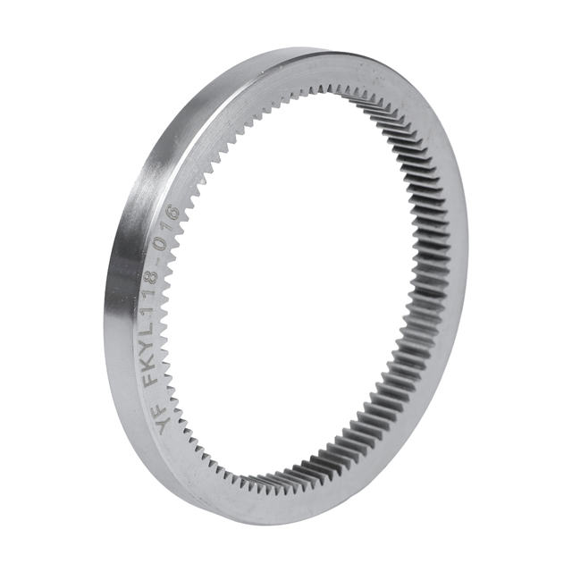
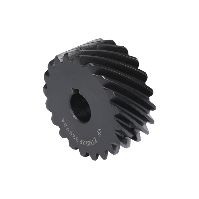
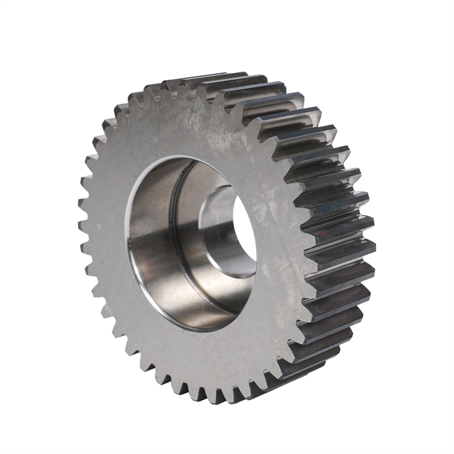
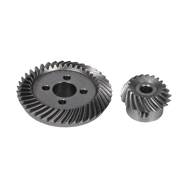
Custom steel spur gear sets for reliable power transmission between parallel shafts. YF Gear supports matched gear and pinion manufacturing with customizable gear ratios, steel grades, tooth geometry, and mounting dimensions.
Key Features & Benefits
Matched Gear & Pinion Design: Compatible tooth geometry and center distance for reliable meshing.
Durable Steel Construction: Carbon steel and alloy steel options for industrial transmission.
Custom Gear Ratios: Tooth counts and transmission ratios tailored to equipment requirements.
Heat Treatment Options: Quenching, tempering, or case hardening according to the selected steel grade.
OEM Gear Set Manufacturing: Drawing-based production with customized bores, keyways, and mounting features.
Customization: OEM / Matched Gear Set Manufacturing
| Availability: | |
|---|---|
| Quantity: | |
A steel spur gear set consists of compatible straight-tooth gears designed to transmit rotational motion and torque between parallel shafts. The driving pinion and driven gear must have matching tooth geometry, appropriate center distance, and suitable material properties to operate as a complete transmission assembly.
YF Gear provides custom steel spur gear manufacturing services for industrial gearboxes, mechanical drive systems, automation equipment, and OEM machinery.
We support drawing-based customization of gear ratios, materials, tooth dimensions, bores, keyways, and mounting configurations to suit different transmission requirements.
A gear set is more than two individual gears. For reliable operation, both components must be designed to mesh correctly under the intended operating conditions.
For a conventional external spur gear pair, the essential matching requirements include:
Matching Parameter | Driving Pinion | Driven Gear | Design Consideration |
|---|---|---|---|
Gear Module | Specified Module | Matching Module | Must be compatible |
Pressure Angle | Specified Angle | Matching Angle | Must match for standard involute gearing |
Number of Teeth | Z1 | Z2 | Determines transmission ratio |
Pitch Diameter | d1 | d2 | Determines nominal center distance |
Face Width | Based on Design | Based on Design | Must provide suitable tooth engagement |
Material | Selected Steel Grade | Selected Steel Grade | May differ according to operating requirements |
Bore Dimensions | Input Shaft Fit | Output Shaft Fit | Determined by shaft configuration |
Tooth Accuracy | Specified Grade | Compatible Grade | Supports required meshing quality |
The driving pinion transfers rotational motion from the input shaft to the driven gear.
For a simple external gear pair, the gears rotate in opposite directions. Their relative rotational speeds depend on the tooth counts.
A smaller driving pinion paired with a larger driven gear provides speed reduction and torque multiplication, subject to transmission losses.
Correct center distance is essential for gear meshing.
For standard, unshifted external spur gears with the same module, the nominal center distance is determined by the sum of their pitch radii.
Backlash must also be considered to accommodate manufacturing tolerances, thermal effects, lubrication, and assembly conditions.
A suitable gear pair should be designed with controlled clearance rather than assuming that zero backlash is always desirable.
Gear ratio is one of the key parameters when selecting a steel spur gear set.
For a simple external spur gear pair, the speed ratio is calculated using the number of teeth:
Gear Ratio (i) = Driven Gear Teeth (Z2) / Driving Pinion Teeth (Z1)
The examples below illustrate how different tooth-count combinations affect transmission speed.
Pinion Teeth | Driven Gear Teeth | Gear Ratio | Typical Function |
|---|---|---|---|
20 | 20 | 1:1 | Equal-speed transmission |
20 | 40 | 2:1 | Speed reduction |
20 | 60 | 3:1 | Greater speed reduction |
24 | 48 | 2:1 | Alternative gear geometry |
25 | 75 | 3:1 | Alternative gear geometry |
These are illustrative tooth-count combinations, not stock product specifications. Final gear geometry must be checked for proper meshing, tooth strength, interference, center distance, and load requirements.
The appropriate transmission ratio depends on the required output speed and torque.
Before selecting a gear set, consider:
Input motor speed
Target output speed
Required output torque
Available shaft center distance
Operating load and duty cycle
Gearbox installation space
Noise and lubrication requirements
Gear ratio selection should be evaluated together with tooth strength, material choice, and the overall transmission design.
Steel material selection influences tooth strength, wear performance, machinability, heat treatment response, and overall component durability.
Different steel grades may be appropriate for different industrial operating conditions.
Steel Grade | Material Characteristics | Common Considerations |
|---|---|---|
45# Steel / C45 | Medium-carbon steel with useful mechanical strength and machinability | General industrial gear components |
40Cr Alloy Steel | Chromium alloy steel with good hardenability | Gears requiring higher strength or suitable surface hardening |
20CrMnTi Alloy Steel | Case-hardening alloy steel | Gear teeth requiring a hard surface and tougher core |
Stainless Steel | Corrosion-resistant material options | Moisture-exposed or corrosive environments |
45# steel is commonly used for mechanical transmission components requiring a practical balance of mechanical strength, machinability, and cost.
Depending on operating requirements, it may be used in a suitable heat-treated condition.
40Cr alloy steel is an option for components requiring increased strength or wear resistance after appropriate heat treatment.
Its suitability depends on gear geometry, loading, required hardness, and manufacturing conditions.
20CrMnTi is commonly considered for gears that require a hardened tooth surface combined with a comparatively tough core.
With suitable carburizing and heat treatment, it can be used in transmission applications where tooth wear and contact fatigue resistance are important.
Material selection must account for the actual gear dimensions, heat treatment conditions, and operating requirements.
Steel gears may require additional processing to improve their mechanical and surface characteristics.
The selected treatment depends on material grade, gear dimensions, and required service conditions.
Quenching and tempering can be used to adjust the strength, hardness, and toughness of suitable steel grades.
The process must be selected according to the required material properties and dimensional stability.
Induction hardening may be applied to suitable steels where localized tooth surface hardness is required.
Treatment feasibility depends on gear size, tooth geometry, steel composition, and equipment capability.
Carburizing is commonly used with appropriate low-carbon alloy steels to produce a hardened surface layer.
It can improve wear and contact fatigue performance when combined with suitable gear design, treatment parameters, and quality control.
Black oxide treatments or other protective finishes may be specified for appropriate steel gear components.
Surface protection requirements should be selected according to the environment, dimensional tolerances, lubrication, and assembly conditions.
Steel spur gear pairs are used in systems requiring positive mechanical engagement and transmission between parallel shafts.
Steel spur gears can form individual reduction or transfer stages within industrial gearboxes.
For these applications, tooth geometry, gear ratio, lubrication, shaft support, and operating loads must be considered together.
Mechanical drive assemblies in packaging and processing equipment may use spur gear sets to synchronize rotational components or transmit motor power.
Gear selection depends on operating speed, duty cycle, load variation, and the required motion relationship.
Automated machinery can incorporate steel gear pairs in actuators, indexing mechanisms, and specialized transmission assemblies.
Appropriate backlash and mounting accuracy help support predictable mechanical motion.
Equipment manufacturers may require custom gear and pinion combinations that are not available as standard catalog components.
Drawing-based manufacturing can accommodate specified tooth counts, shaft fits, material grades, and mounting features.
Manufacturing individual gears to the required dimensions is only one part of producing a compatible gear set.
The complete pair should also be evaluated according to its mating geometry and intended assembly conditions.
Before production, the gear drawings and specifications should be reviewed together.
Important items include:
Module and pressure angle compatibility
Tooth-count combination
Center distance
Backlash requirement
Material and heat treatment
Bore and keyway tolerances
Operating speed and torque
Steel gear blanks are prepared according to the required material and geometry.
Gear teeth are produced using a suitable machining process, such as hobbing or shaping where applicable.
Critical dimensional features are machined according to the approved drawings.
Depending on the project, heat treatment and finishing may be required to achieve the specified mechanical properties and dimensional requirements.
Potential distortion from heat treatment should be considered during process planning.
Inspection requirements may include:
Inspection Item | Purpose |
|---|---|
Tooth Profile | Verify tooth geometry |
Tooth Pitch | Evaluate tooth spacing consistency |
Radial Runout | Assess eccentricity |
Bore and Keyway | Verify shaft fit requirements |
Surface Hardness | Check specified heat treatment characteristics |
Center Distance | Confirm assembly geometry |
Backlash | Evaluate specified clearance |
Tooth Contact Pattern | Assess meshing conditions where required |
Inspection scope and reporting requirements should be agreed before manufacturing.
YF Gear supports custom gear manufacturing for industrial equipment companies seeking transmission components based on specific mechanical designs.
Possible customization requirements include:
Transmission Geometry
Custom module, tooth counts, pressure angles, gear ratios, and center distances.
Gear Body Configuration
Custom bores, keyways, hubs, flanges, and mounting structures.
Materials and Treatments
Specified carbon steel or alloy steel grades, heat treatment requirements, and compatible surface finishes.
Production Requirements
Drawing-based prototypes, replacement parts, and production quantities subject to project feasibility.
When replacing an existing gear pair, it is important to evaluate both gears rather than only the visibly damaged component.
Excessive wear, incompatible tooth geometry, or incorrectly specified center distance may affect the service performance of a replacement set.
Customers can provide existing drawings, gear samples, or measured specifications to support the manufacturing review.
To request a quotation for a custom steel spur gear set, please provide the following information.
Requirement | Information Needed |
|---|---|
Gear Drawings | Pinion and driven gear drawings |
Module / DP | Tooth size specification |
Tooth Counts | Pinion teeth and driven gear teeth |
Gear Ratio | Target transmission ratio |
Center Distance | Specified shaft spacing |
Material Grades | Required steel grades |
Bore and Keyway | Shaft mounting requirements |
Face Width | Required gear width |
Heat Treatment | Required hardness and process |
Accuracy Requirements | Applicable standard and grade |
Quantity | Number of sets |
Operating Conditions | Speed, torque, lubrication, and environment |
If a complete technical drawing is unavailable, providing an existing sample and basic operating requirements can help establish the information needed for further evaluation.
A steel spur gear set is a group of compatible straight-tooth gears, commonly a driving pinion and a driven gear, designed to transmit motion and torque between parallel shafts.
For a simple external gear pair, the gear ratio is determined by the number of teeth on the driven gear divided by the number of teeth on the driving pinion.
Conventional external involute spur gears generally require matching modules and compatible pressure angles for correct meshing. Different modules should not be assumed to be interchangeable.
The best steel depends on the transmitted load, working conditions, manufacturing requirements, and heat treatment. Common options include 45# steel, 40Cr, and 20CrMnTi.
Not necessarily. Backlash is normally specified according to the requirements of the complete transmission system. A precision gear set can still require intentional clearance for reliable operation.
Yes. Custom gear manufacturing can be based on technical drawings, gear samples, or suitable dimensional data. The mating gear geometry and operating requirements should be reviewed together.
Ideally, provide drawings for both gears, including tooth counts, module, pressure angle, center distance, materials, mounting dimensions, and required quantity.
Looking for a steel spur gear set manufacturer for your industrial gearbox or custom machinery project?
YF Gear supports drawing-based steel gear manufacturing, including gear and pinion combinations with specified transmission ratios, materials, mounting features, and accuracy requirements.