

loading


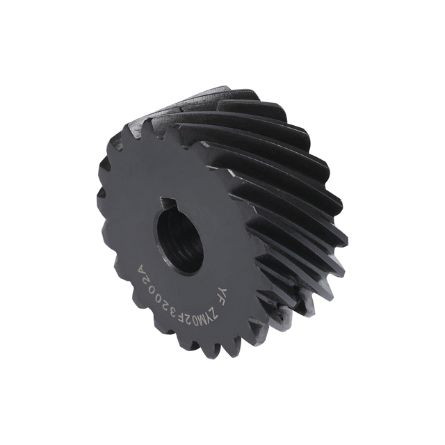
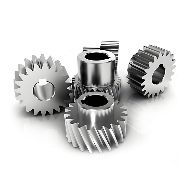
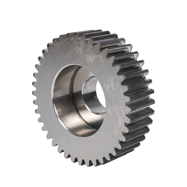
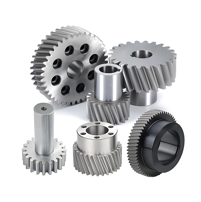
YF Gear provides custom precision spur gear components for automation systems, precision mechanisms, and industrial equipment. We support drawing-based manufacturing with attention to gear tooth geometry, dimensional tolerances, and shaft compatibility.
Key Features & Benefits
Precision Tooth Geometry: Gear profiles and tooth spacing manufactured to drawing requirements.
Dimensional Accuracy: Controlled bore, face width, concentricity, and mounting dimensions.
Custom Gear Configurations: Module, tooth count, pressure angle, and hub designs tailored to your assembly.
Material Flexibility: Steel, stainless steel, and other suitable materials based on application needs.
OEM Machining Support: Custom manufacturing for precision equipment and mechanical transmission assemblies.
Customization: OEM / Drawing-Based Manufacturing
| Availability: | |
|---|---|
| Quantity: | |
When a mechanical assembly requires consistent rotary transmission, accurate shaft positioning, and controlled gear engagement, the dimensional quality of its gear components becomes especially important.
YF Gear provides custom precision spur gear components for industrial automation, machinery assemblies, robotic mechanisms, and precision transmission equipment.
Our drawing-based manufacturing approach focuses on the gear characteristics that matter to assembly performance, including tooth geometry, pitch accuracy, bore dimensions, concentricity, and mounting tolerances.
We work with equipment manufacturers and engineering teams to produce precision gear components based on their specified materials, geometry, and inspection requirements.
The accuracy of a spur gear is determined by more than its overall dimensions.
Tooth geometry, pitch consistency, runout, and mounting features all influence the way a gear engages with its mating component.
For precision applications, these characteristics should be defined through engineering drawings and applicable gear accuracy standards.
Accuracy Parameter | What It Controls | Why It Matters |
|---|---|---|
Tooth Profile Deviation | Difference between the actual and specified tooth profile | Influences tooth contact and transmission behavior |
Tooth Pitch Deviation | Variation in tooth spacing | Affects rotational consistency |
Helix / Lead Deviation | Variation in tooth direction across the face width | Influences load distribution |
Radial Runout | Gear eccentricity relative to a defined reference axis | Can contribute to transmission variation |
Bore Tolerance | Dimensional accuracy of the shaft mounting hole | Affects assembly fit |
Concentricity / Coaxiality | Alignment between specified cylindrical features | Supports proper component alignment |
Surface Finish | Condition of machined tooth and mounting surfaces | Can influence friction, wear, and contact behavior |
The required accuracy depends on the application, speed, loading conditions, gear size, and mating component.
For precision spur gears, accurate tooth shape and spacing are essential to predictable meshing performance.
Profile deviations can change the contact pattern between mating gear teeth, while pitch variations can contribute to transmission error.
These characteristics are particularly relevant in equipment requiring consistent movement or repeated positioning.
Even accurately machined teeth may not perform as intended if the gear is poorly aligned with its shaft.
Bore diameter, mounting faces, hub geometry, and reference surfaces should be specified according to the assembly requirements.
Depending on the design, mounting options may include:
Precision round bores
Keyways
D-shaped bores
Integrated hubs
Flanged gear bodies
Custom mounting holes
The appropriate fit should be determined using the shaft dimensions, material properties, and operating conditions.
Precision spur gears can be customized in different sizes and configurations to match the intended transmission assembly.
Parameter | Available Design Requirements |
|---|---|
Product Type | Precision Spur Gear Components |
Gear Configuration | External Straight-Tooth Spur Gear |
Module / Diametral Pitch | According to Engineering Drawings |
Number of Teeth | Customized |
Pressure Angle | According to Gear Design |
Pitch Diameter | Drawing-Specified |
Face Width | Customized |
Material | Carbon Steel, Alloy Steel, Stainless Steel or Approved Alternatives |
Bore Type | Round Bore, Keyway, D-Bore or Custom |
Gear Accuracy Grade | According to Agreed Drawing / Standard |
Dimensional Tolerances | Defined by Critical Features |
Heat Treatment | Where Required by Material and Application |
Surface Finish | According to Specification |
Manufacturing | Custom / OEM |
Inspection Requirements | Based on Drawing and Purchase Agreement |
The achievable accuracy and manufacturing method depend on the combined gear dimensions, material, machining process, and inspection requirements.
A precision spur gear must be compatible with the complete mechanical system, not only the individual gear drawing.
We recommend evaluating three important design relationships.
The gear module, tooth count, pressure angle, and profile modification determine the basic meshing geometry.
For a standard external spur gear pair, the mating gears normally require compatible modules and pressure angles.
The center distance must also account for the selected tooth geometry and any intended profile shifts.
Backlash is the clearance between mating gear teeth.
A suitable amount of backlash helps accommodate manufacturing variation, lubrication, temperature changes, and operating loads.
For precision positioning mechanisms, backlash requirements should be considered alongside tooth accuracy, bearing clearances, shaft stiffness, and assembly tolerances.
High precision does not automatically mean zero backlash. The appropriate clearance depends on the complete mechanism.
Material selection affects stiffness, strength, thermal expansion, wear resistance, and machinability.
For example, steel gears may be selected for strength and rigidity, while stainless steel may be considered when corrosion resistance is required.
Any heat treatment must also account for possible dimensional changes and the need for subsequent finishing operations.
Precision spur gears can be used in mechanisms where rotational consistency, controlled movement, and compact gear arrangements are important.
Precision spur gears can transmit rotary motion in automated actuators, indexing mechanisms, and positioning assemblies.
Typical design priorities include dimensional consistency, mounting accuracy, and appropriate backlash.
Robotic and electromechanical systems may use compact spur gear stages where controlled movement and repeatability are important.
Gear accuracy must be considered together with motor control, shaft support, and overall assembly stiffness.
Mechanical instruments and measuring assemblies may require small gears with consistent tooth geometry and controlled mounting dimensions.
In these applications, gear manufacturing tolerances can affect the behavior of the complete motion mechanism.
Precision spur gear components may be used in gear reduction assemblies where predictable meshing and space-efficient parallel-shaft transmission are required.</escape>
Precision gear manufacturing involves coordinating gear body machining, tooth generation, finishing, and dimensional inspection.
The exact process depends on the required accuracy grade, material, geometry, and production quantity.
Gear blanks are machined to establish the required reference surfaces, bore geometry, outside features, and mounting dimensions.
These reference features are important because later tooth processing and inspection depend on stable, repeatable datum locations.
Tooth generation may involve gear hobbing, shaping, or other suitable machining methods.
Process selection depends on tooth geometry, workpiece access, material, production requirements, and achievable accuracy.
Where specified, additional finishing operations may be required to meet surface finish or dimensional requirements.
For applications with demanding accuracy requirements, finishing should be selected with reference to the tooth geometry and material condition.
Finished gears are evaluated against the agreed dimensional requirements.
The inspection plan may include bore measurement, runout, tooth geometry, and other critical characteristics specified in the engineering drawing.
Precision gear manufacturing requires a defined inspection strategy.
Instead of relying only on general dimensional checks, engineering teams should identify which characteristics directly influence assembly function.
Critical dimensions can include:
Bore diameter
Outside diameter
Face width
Hub dimensions
Mounting hole positions
Reference surface geometry
Depending on the accuracy requirements, gear inspection can include tooth profile, pitch deviation, lead deviation, and runout evaluation.
Specialized measuring equipment may be necessary when a defined gear accuracy grade is specified.
For OEM projects, buyers may specify particular inspection records or acceptance criteria.
Providing the applicable drawing revision, tolerance requirements, and inspection expectations before production helps reduce misunderstandings.
Note: Specific gear accuracy grades, inspection equipment, and certification claims should be confirmed for the individual manufacturing project.
Providing complete technical information helps determine manufacturing feasibility and allows a more accurate quotation.
Technical Information | Recommended Details |
|---|---|
Gear Drawing | 2D technical drawing or 3D CAD model |
Gear Geometry | Module, tooth count, pressure angle, profile shift if applicable |
Gear Dimensions | Pitch diameter, face width, bore and hub dimensions |
Accuracy | Required gear grade and applicable standard |
Material | Material grade and condition |
Heat Treatment | Process, hardness and depth requirements if applicable |
Mating Gear | Geometry and assembly relationship |
Operating Conditions | Torque, speed, duty cycle and environment |
Inspection | Critical dimensions and reporting requirements |
Order Quantity | Prototype, trial batch or production volume |
Sharing the mating gear drawing can be particularly useful when tooth engagement and assembly alignment are critical.
A precision spur gear is manufactured and inspected to defined accuracy requirements. These may include controlled tooth profile, pitch, runout, bore dimensions, and mounting features. The appropriate precision level depends on the intended application.
Gear accuracy describes how closely the manufactured gear conforms to specified geometry. Backlash is the clearance between mating gear teeth. An accurate gear can still have intentional backlash, depending on the design.
Yes. Custom gear manufacturing can accommodate drawing-defined modules, tooth counts, bores, face widths, and mounting features, subject to manufacturing feasibility.
The applicable standard depends on the project requirements. Common gear accuracy systems include ISO and AGMA standards. Buyers should identify the relevant standard, edition, quality grade, and required inspection characteristics.
They can be suitable for robotic and automated mechanisms that use parallel-shaft gear transmission. Selection should account for operating torque, backlash, positioning accuracy, load cycles, and assembly stiffness.
YF Gear supports drawing-based gear component manufacturing. Customers can submit drawings, technical requirements, and estimated order quantities for feasibility review and quotation.
Looking for a manufacturer of precision spur gear components for your machinery or automation project?
YF Gear supports customized gear manufacturing according to customer drawings, required geometry, materials, and critical dimensional specifications.
Send your technical drawings and quantity requirements to discuss your project.